Metal Injection Molding Design
Metal Injection Molding Design
In order to take full advantage of Metal Injection Molding process, we need to consider many critical aspects in MIM design. A clear understanding of these principles will guarantee the best manufacturing results for your MIM parts. In addition, we will assist you to analyze benefits versus cost in MIM designing stage.
MIM design guideline is a reference to apply new components design principles, and evaluate exist components manufacturing possibility. Proper MIM design will maximize economic benefits, guarantee MIM parts with targeted geometries and dimensions.
Design for Manufacturing
In MIM designing process, you need to consider the Design for Manufacturing principles, in order to eliminate any expensive secondary operations.
Sintering Support
In sintering process, green parts shrink about 20% in volume. In order to minimize distortion possibility, we need to support green parts adequately.
It is ideal to design MIM part with large flat surface, or several components with a common plane, so we can use standard fixture. Otherwise, we require part-specific fixtures or setters for parts with long spans, cantilevers, or delicate points.
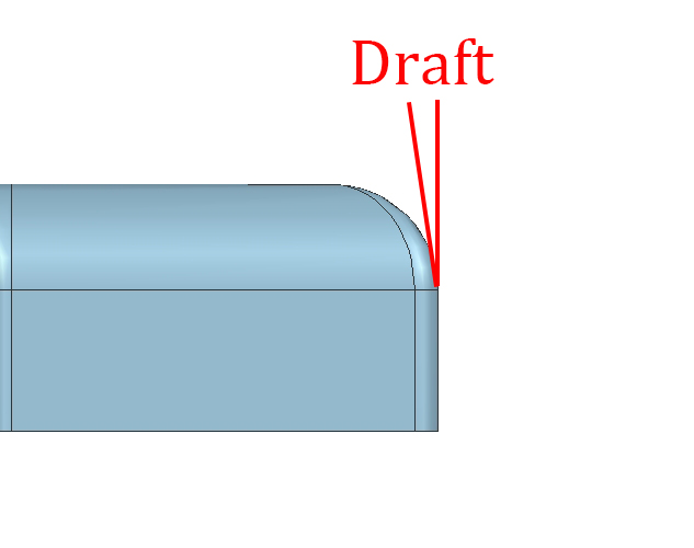
Draft Angle
This is a small angle on parts surface, which is parallel to mold movement direction. Draft is used to facilitate molded form release and ejection. Its normal range is 0.5°to 2.0°, greater draft should be used once loner component element with text on surface.
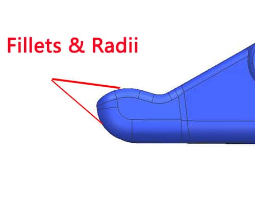
Fillets and Radii
We normally apply fillets and radii to reduce feature intersection stress for production function. They are instrumental in the molding process, eliminating sharp corners, feedstock flow, and ejection marks. It is an effective way to handling sharp corners. Fillets and radii of 0.4–0.8 mm are generally preferred.
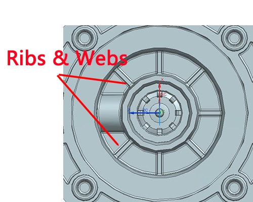
Ribs and Webs
Ribs and webs are normal features to reinforce relative thin walls and avoid thick section. In addition, they can improve material flow, limit distortion, and increase thin wall strength and rigidity. Rib thickness should be less than adjoining wall, otherwise, we should apply multiple ribs for structural requirement.
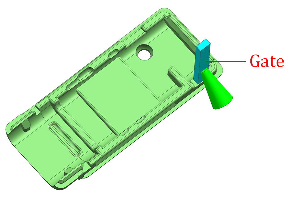
Gating
As the injection gate always leaves a mark on a finished part, so its location should balance demand of manufacturability, function, dimensional control and esthetic. Its best location is on parting line of mold, this position will make flow path impinges on cavity wall or core pin. We need to consider other factor of gate location, such as subgate, pinpoint gate and tunnel gate. For MIM parts with different wall thickness, we will place the gate at the thickest cross-section, in order to make MIM material flows from thick to thin section. This way will reduce voids, sink marks, concentration stress and flow line on part surface. In multiple cavities MIM process, we must consider gate size and placement to assure MIM material delivery to each cavity at balanced fill rate.
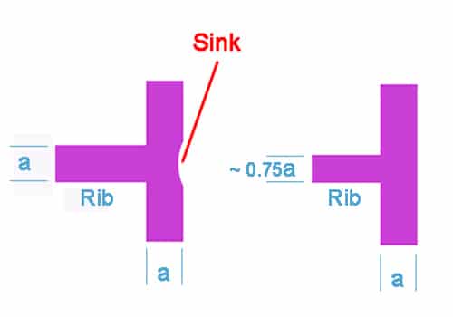
Sink
Minimize sink and knit lines in design process. Sink always occurs around the thick section of same thickness wall and rib. Reduce rib thickness to 75% of wall will eliminate potential sink.
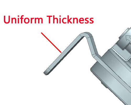
Uniform Wall Thickness
MIM parts overall size and design will determine cross-sectional wall thickness. Generally, optimum wall thickness is 1 mm to 6 mm, which is variable for different overall size. We should uniform wall thickness in feasible condition, in order to avoid non-uniform shrinkage, distortion, internal stress, voids, cracking, sink marks, dimensional and tolerance interference lead by thickness variations. Thickness of 1-6 mm is preferred. We still can remove material in both direction to create wall thickness uniformity, in order to save cost of fine metal powder in economical way.
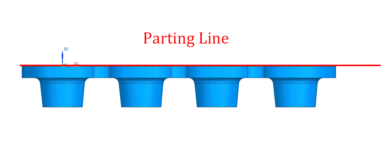
Parting Line
A parting line is the plane where two halves of a mold meet, all features need to be perpendicular to the parting line for removal to facilitate from mold. Normally, parting line will transfer to part surface as witness line, we can design parting line to separate along inconspicuous edge to hiding it. It is preferred to contain the parting line in one single plane.
Design of Part Improvement
We also notice the Design of Part Improvement as following:
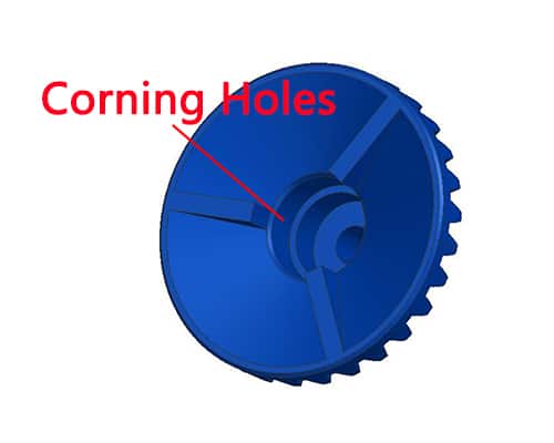
Coring Holes
Coring holes are normally used to reduce MIM parts cross-section, uniform wall thickness, reduce metal material consumption, reduce or eliminate secondary machining operation. Its preferred direction is parallel to mold opening and perpendicular to parting plane. When length/diameter ratio is greater than 4:1, the through hole is preferred because both ends support the core pin, otherwise, blind holes will be used with the cantilevered pin.
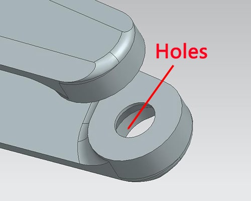
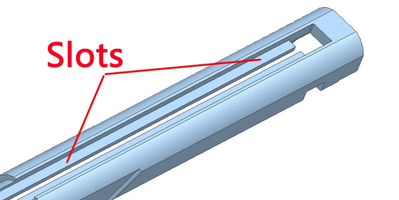
Holes and Slots
Hole and Slots can provide functional features in MIM parts without additional cost, besides reduce part mass and uniform wall thickness. Holes are perpendicular to parting line is easy to mold with the least cost, these are parallel require mechanical sliders or hydraulic cylinders. For internal connected holes, we need to consider carefully of potential sealing-off problems and flashing issues.
Undercuts
External undercuts are easy to form on a parting line by split mold. While internal undercuts only can be produced by slides, or collapsible cores. In MIM design, we should avoid internal undercuts because of additional cost and potential flashing problems.
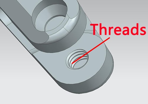
Threads
Both internal and external threads can be formed in MIM process, internal thread is more precise and cost-effective than unscrewing cores. The optimum location of external threads is on a parting line. To hold thread tolerance on thread diameter, narrow flat is typically 0.005”.
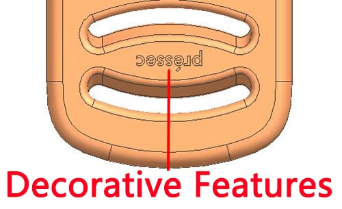
Decorative Features
MIM can easily mold features as logo, knurl, part number and identification marks in place without added cost, all these feature can be raised or sub-surface. We also can pride high level feature detail like diamond knurling in MIM process.
Thickness Transition
Although MIM part wall thickness is uniformed desirably, coring for thickness uniformity is not a perfect option, and it is difficult to avoid variations. We need to design a gradual transition between different thickness.
