Fe50Co Electronic MIM Case
Introduction
Fe50Co soft magnetic alloy has high saturation magnetic induction and high Curie temperature. Therefore, it is applied as a ferromagnetic element with high BS and temperature requirement. Especially in electromagnet pole heads, relays, force rejection rotors, power transformers, magnetostrictive transducer cores, micro and specific motors with light weight, small size and high operating temperature.
With the development of magnetic circuit components in miniaturization and multi-function, the component size is becoming smaller and smaller, and the component geometry is more and more complex. Because the Fe50Co alloy is expensive, brittle and poor processing performance, the traditional method of CNC machining has the disadvantages of large waste, long cycle time, high cost and low efficiency.
Therefore, Metal Injection Molding is a low-cost technology for Fe50Co production with micro processing. This cost-effective method will save both energy and resources in manufacturing process. ZCMIM provide Fe50Co material in our MIM manufacturing, in order to satisfy specific requirements in electronic industry.
Fe50Co Materials Analysis
Iron base MIM feedstock are the most critical materials in electronic industry. Regardless of physical properties like yield strength, tensile strength, elongation etc. There are some specific requirements of electronic part with high magnetic permeability. Especially for application of voltage changer, current transformer, micro motor.
Fe50Co Composition :
| Fe50Co | Iron | Chromium | Cobalt | Manganese | Silicon | Carbon |
| Percent by Weight | Bal. | 0-0.2 | 49-51 | 0-0.3 | 0-0.3 | 0.04 |
Fe50Co Characteristic Properties:
| Material | Density | Tensile Strength | Yield Strength(0.2%) | Hardness | Elongation (% in 25.4 mm) | Permeability | Magnetization Intensity |
| Fe50Co | ≥7.95g/cm³ | ≥300Mpa | ≥180Mpa | 80HRB | 1% | μmax =5200 | Js(4Ka/m)=2.0T |
Iron cobalt alloys are soft magnetic materials with about 50% cobalt containment. These alloy have the extreme high saturated magnetic flux density (BS) of 2.0T, and Curie temperature between 980 and 1100 ℃. Therefore, cobalt-iron alloys are suitable for lightweight application with small size and high temperature. Such as specific micro motors, electromagnets, electric relay, voltage changer, current transformer etc. In addition, the large saturation magnetostriction coefficient (λs) make it applied for magnetostrictive transducer.
Comparing to iron nickel alloys, iron cobalt alloys have poor machinability, easy oxidation and low resistivity. Furthermore, iron cobalt alloys have large loss in high frequency, so it is not suitable to work at high frequency. Because of high cost of cobalt alloy, it is mostly applied in high torque motors, electromagnet poles, eardrum vibrators, power transformers, magnetostrictive transducers, etc.
Design Analysis
Metal Injection Molding (MIM) technology will not only provide higher freedom in geometry design, but also control high tolerance in various dimensions.
Suggest Tolerance
Consider the sintering process in MIM, non-isotropic shrinkage result in tight deformation. Therefore, our engineering team will present suggest tolerance in design analysis.
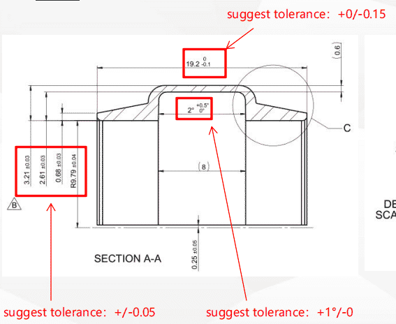
As we notice in the above graphs, we normally emphasize the nominal balanced tolerance option of ± 0.05 mm for common MIM parts. For total length of 19.2 mm in this case, we apply shaping mold to control tolerance of +0/-0.15 mm. These suggest tolerance are critical for further assembly with strict dimension requirement.
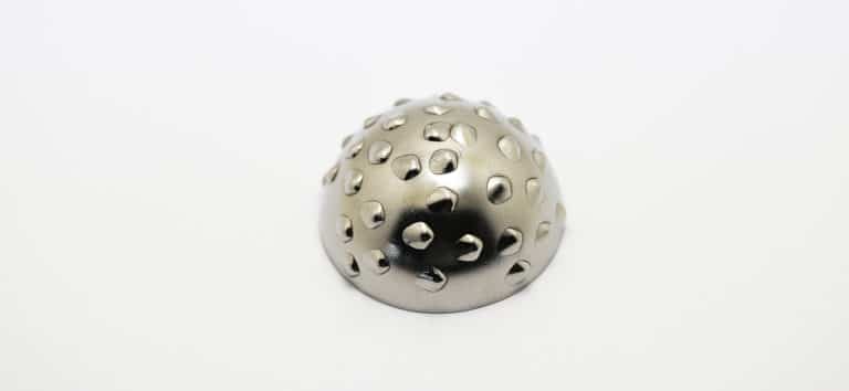
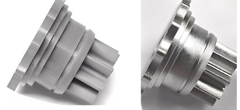
MIM Part Geometry
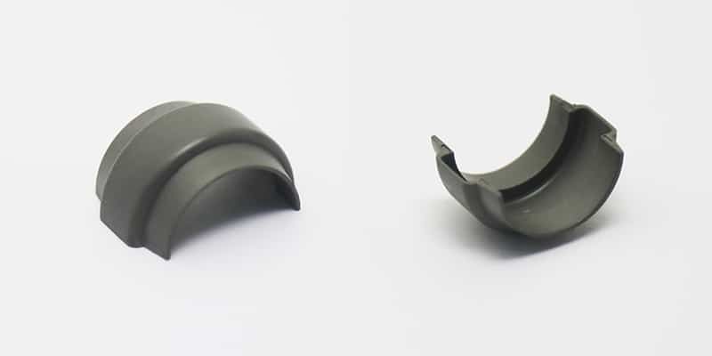
In this MIM part, it is an obvious half circle shell with different wall thickness. The only challenge is thin wall thickness of 0.6 mm with ±0.05 mm tolerance. We need to consider the shrinkage issue in both debinding and sintering. In addition, the secondary process of shaping is required to adjust final dimension and tolerance.
Mold Design and Manufacturing
Mold design and manufacturing is a critical step in MIM, the mold design will determine the final injection molded parts (green parts). Different structure and geometry design can achieve various molding requirements.
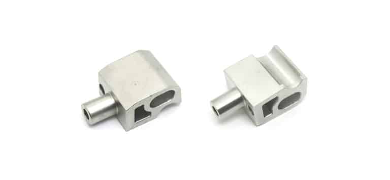
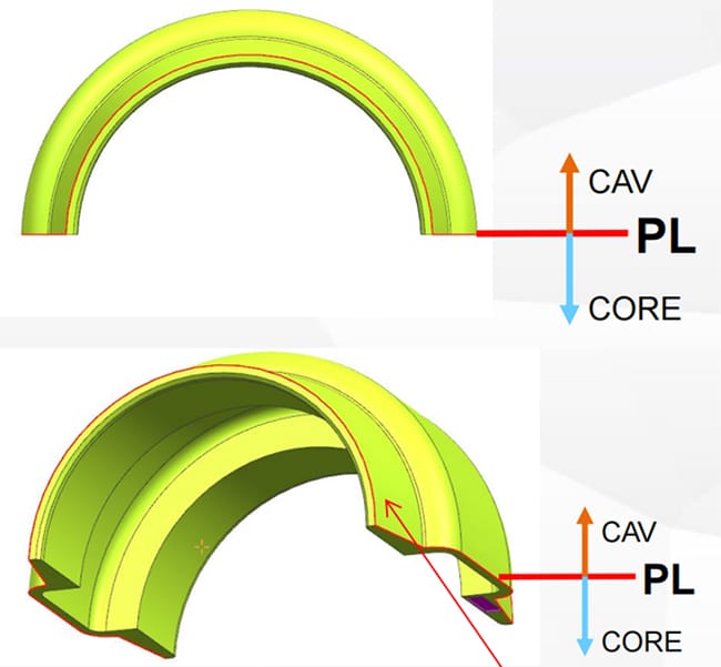
Parting Line
From the structure in design, it is easy to determine the parting line in mold design. As in the following picture, we can find an obvious parting line in this symmetric structure.
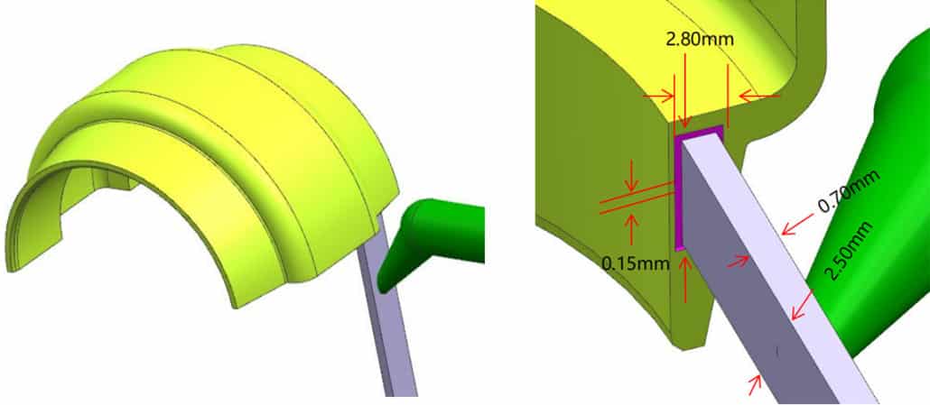
Injection Gate
In reason of the symmetric half-circle structure in this part, we need to avoid gate marks in injection molding. Sug-gate is applied in mold design, this kind of gate can eliminate the effect of injection molding gate, such as flashing, marks, and crater size. In the following picture, we can notice that the crater size is only 2.8×1.0×0.15 mm.
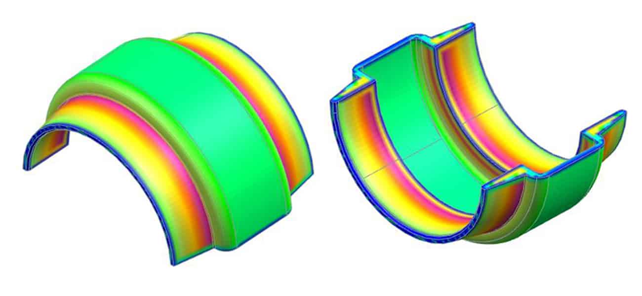
Thickness Analysis
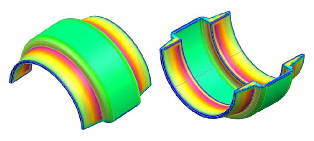
From the thickness analysis, we can notice that the minimum thickness is only 0.60 mm, while the maximum thickness is 1.71 mm. However, the overall thickness of this part is relatively even, there is low risk of shrinkage in the red area.
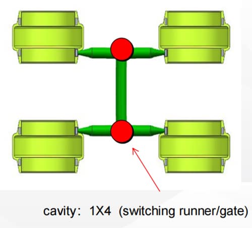
Cavities Ranking
In order to improve the production efficiency, we always apply the multiple cavities. This method will improve the injection molding productivity by several times. However, in order to avoid insufficient injection defects, we should apply switching runners or gates in this project.
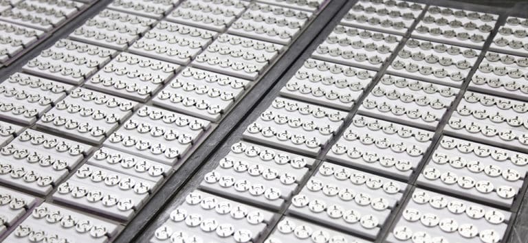
Fe50Co Debinding
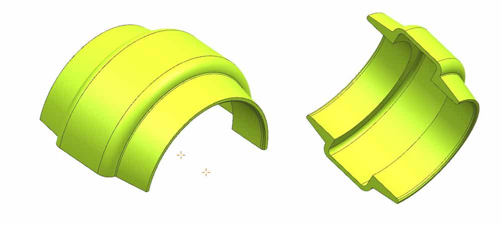
As we apply Fe50Co feedstock in this project, the catalytic debinding method will result in high debinding efficiency. In addition, because of the limited thickness of green parts, and its smooth thickness transition. We should also avoid excessive debinding of green parts. From the following plating picture, we can notice that over-debinding will give rise to deformation of yellow parts, and finally result in crack and fracture.
In this case, we apply the debinding temperature at 120 ℃, which is lower than normal temperature at 150 ℃. The debinding time is about 10 hours, there is a minimal wet loss of 10.5% after that.
Fe50Co Sintering
Although metal injection molding is the most cost-effective metalworking method for Fe50Co magnetic alloy. There are still some defects we need to consider, such as porosity in structure will result in low density of final sintered products. The relative density of 95%~96% is difficult to achieve high saturation magnetic induction. Our normal testing result can reach to BS 1.8T. In this case, additional processes are required to increase final sintering density. In order to achieve high density (98%) and saturation magnetic induction (BS 2.3T) for requirement.
The typical sitnering parameter:
- Sintering Atmosphere: 100% Argon (Ar)
- Sintering Substrate: Non-metallic Plate (Al2O3,Ceramic)
- Sintering Temperature: 1370℃
- Sintering Time: 15 hours
Sintering Process
Our typical sintering process of Fe50Co materials are following:
Negative Pressure Degreasing
In this process, the temperature in the furnace is increased from room temperature to 600℃. In addition, we also need to apply multi-stage holding temperature with vacuum pressure. Therefore, we must remove the remaining binder materials in this stage. The total time of negative pressure degreasing is around 450 min.
Vacuum Sintering
The furnace temperature will increase from 600℃ to 850℃ at a rate of 3℃/min. Then holding the temperature at 850℃ for a period of time. This vacuum sintering is critical for the controlling of carbon content. Normally, we apply this process to ensure the carbon content of final sintered products.
Partial Pressure Sintering
We will increase the furnace temperature from 850℃ to 1050℃ at a rate of 3℃ per minutes. Then hold this temperature for a short time, which is depended on different MIM materials. After that, increase the furnace temperature to 1370 ℃ at the same rate, this step is very important for metal powder densification.
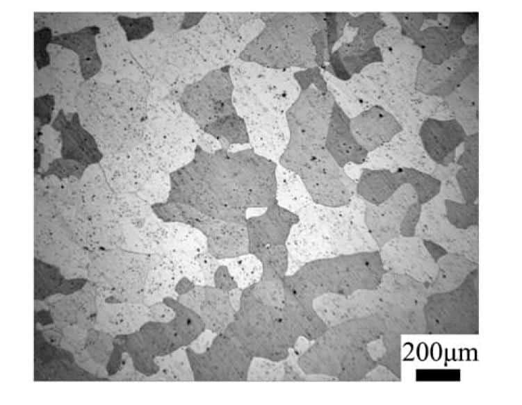
Cooling
In this step, the cooling rate will affect micros-structure of sintered parts. Then affect the final properties of sintered parts.
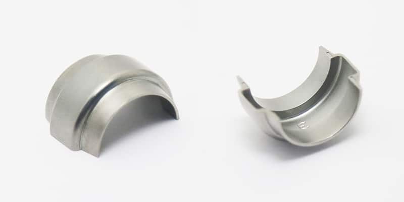
Shaping for High Tolerance
From the plating style in following, we can notice that the gravity will cause delight deformation in debinding and sitnering. In this case, an additional process of shaping is critical to ensure the requirement of final parts’ tolerance
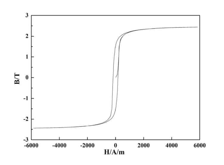
Conclusion
From the following hysteresis loop diagram, the final Fe50Co products achieve the maximum saturation magnetic induction (Bs≥2.3T). This satisfies the customer’s requirement of magnetization Intensity.
If you have special requirement of unique property, contact our engineering team for professional information.