Optical Instrument Case
Introduction
Optical instruments have high precision in the critical dimensions, in order to satisfy the further functions of observation, recording and analysis. Metal injection molding technology has nominal tolerance in the rage from 0.3% to 0.5%. However, these tolerance arrangements are not acceptable in optical instruments. In this case, we can apply CNC machining to improve the accuracy in specific dimension.
Metal injection molding has high efficiency in mass production with complex geometries. But its tolerance is limited by uncontrollable and unpredictable errors in the whole metal manufacturing process. No matter injection molding, debinding, or sintering, secondary treatments. We can only control a typical tolerance of 0.05 mm in absolute dimension. Otherwise, the best possible tolerance of 0.025 mm is very difficult to control in mass production.
CNC machining is a traditional metalworking technology, it has high precision than any other metalworking methods. Because CNC machining apply common electronic system to control different tools, it has some design restrictions like CNC process mechanic, tool geometry and tool access. Therefore, CNC machining is not a cost-effective method for mass production with complex structure.
We apply MIM technology to produce complex sintered parts, then apply CNC machining to improve tolerance in the critical dimensions. ZCMIM can combine these two different metalworking technology with according requirements, then provide our customers the highest quality of MIM parts.
Stainless steel 304 Materials
We have two typical stainless steel 304 materials: stainless steel 304H, stainless steel 304LE. The carbon content is the main difference between these two MIM materials, 304H has high carbon content of 0.08%, while 304LE only has carbon content of 0.03%. Higher carbon content in 304H results in higher hardness of 150-200HV10 than 304LE of 100-150HV10. Otherwise, 304LE provides better corrosion resistance than 304H. It can pass 48 hours salt spray test, while 304H only can pass 24 hours.
In this case, regardless of normal tensile and yield strength, corrosion resistance is another consideration in material selection. Stainless steel 304LE is the perfect MIM material.
Design Analysis
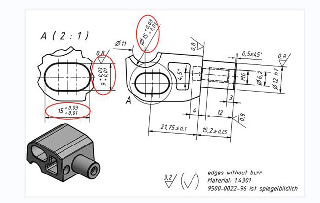
From the original 2D drawing, we can notice that there are three dimensions with higher tolerance requirement. In addition, these 3 tolerances are not in nominal arrangement, but in range of +0.01 to +0.03. This accuracy arrangement is impossible to control perfectly in metal injection molding process. Therefore, additional CNC machining is required to achieve this tolerance.
Tolerance Adjustment
Meanwhile, in order to accelerate the further CNC machining operation, we will adjust the final CNC tolerance in the following picture. It is effective to apply hole base tolerance standard in CNC machining – H7. In this design, we can convert these tolerances to common standard as following:
9H7 means dimension tolerance of -0.00 mm, +0.015 mm,
15H7 means dimension tolerance of -0.00 mm, +0.018 mm,
Φ15H7 means hole diameter tolerance of -0.00 mm, +0.018 mm.
It is obvious that, this tolerance method will not satisfy customer request, but also increase final efficiency of CNC machining operation.
Mold Design & Manufacturing
Critical Area Thickness
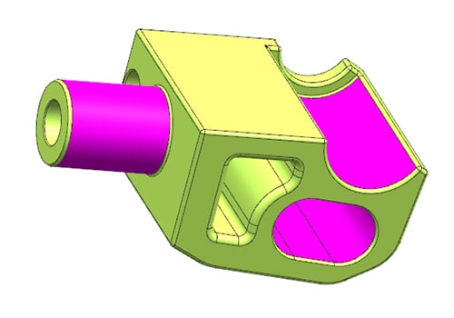
In CNC machining process, the redundant metal materials will be removed or cut by CNC tools, then achieve required tolerance in holes and axle diameter. Therefore, in order to satisfy the final CNC operation requirement in process, we should add 0.5 mm thickness in MIM injection molding process. These slight thickness increases will result in 0.2-0.4 mm thickness increase of final sintered parts. Then CNC machining technology will measure and eliminate the additional metal materials. Finally, achieve tolerance standard of H7 & h7.
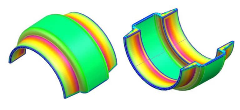
Thickness Analysis
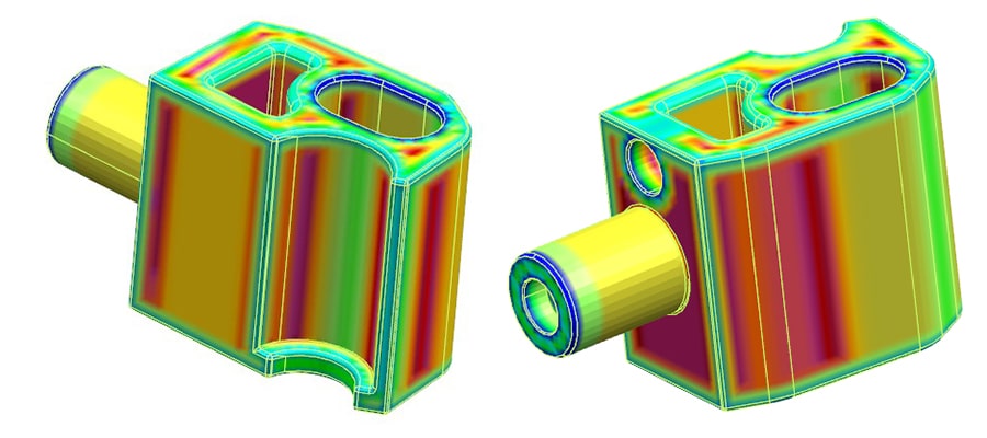
From the 3D drawing, the average thickness in design is 3.42 mm, while the maximum thickness is 6.27 mm. There are high risk of shrinkage in red areas, we should notice these areas after injection molding process. In this case, we need the additional appearance inspection in pilot production, and try to eliminate these shrinkage issues as early as possible.
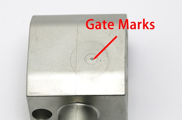
Injection Gate Marks
In 3D drawing analysis, the injected part weight is approximate 107 gram. This is far heavier than the typical MIM process. Therefore, we need to determine the perfect injection gate location, and ensure the smooth process of injection molding.
In this project, we apply direct injection gate with size of 1.5 mm. This kind of gating will leave streaky marks on the injection surface, these marks are difficult to remove by grinding. However, the gate marks won’t affect function of final parts, only left visible trace on the surface.
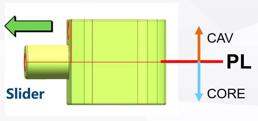
Parting Line
It is easy to determine the parting line in this project, this part has generally symmetrical structure. Therefore, the parting line is the center line of structure in the following picture. In addition, because the total injected part weight is almost 113 gram, this requires higher ejection force than normal size. This parting line position will not only ensure symmetric structure, but also reduce ejection force.
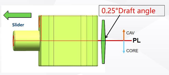
Draft Angle
In reason of the estimate weight of 113gram, it requires higher reject force than typical MIM parts of 10 to 30 gram. On the other hand, too high reject force will give rise to slight deformation of injected parts. This will result in structure defect on final parts. Therefore, draft angle is required to reduce reject force into appropriate arrangement. Make sure that there is no potential risk in the ejection step. We add 0.25° draft angle on both side of parting line, detail information is in following picture.
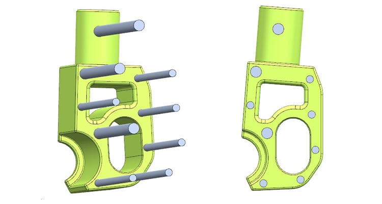
Ejector Pins
We apply 9 pieces of ejector pins to ensure the average fore on ejector pins. In order to minimize the potential of parts’ deformation. Consider the total weight of 113 gram, 9 ejector pins are sufficient for the final ejection in injection molding process.
Debinding & Sintering
Catalytic Debinding
In the thickness analysis, there is a maximum thickness of 6.27 mm. This thickness result in high challenge in debinding process. However, we apply catalytic debinding method to avoid all these issues. Catalytic debidning can ignore any thickness limitation, its high debound efficiency will finish this process in almost 10 hours at temperature of 120℃.
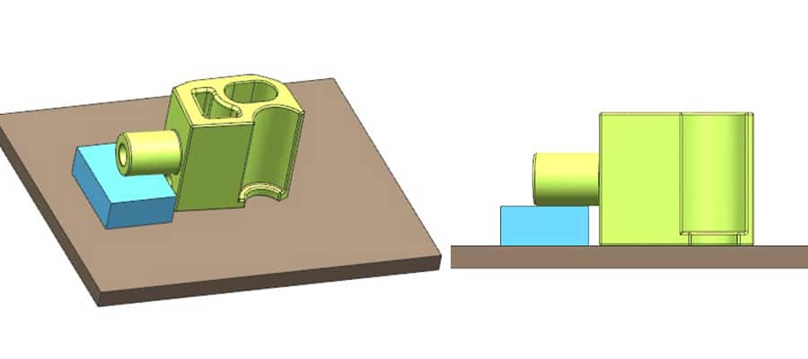
Plating Method
Consider the structure of this part, we should apply custom ceramic block to avoid any deformation issues. From the following picture, the ceramic block can support the cylinder area. In order to eliminate the affection of gravity in debinding and sintering process.
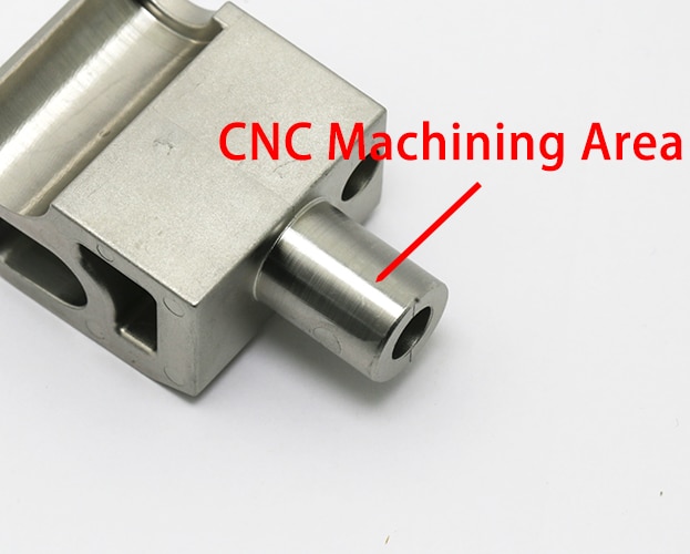
CNC Machining
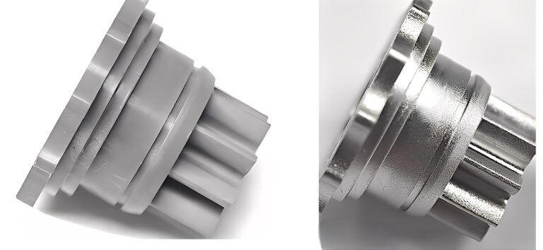
After sintering, the MIM parts will shrink into required dimension in MIM design. However, because of the limitation in metal injection molding, its highest tolerance cannot reach the requirement in this case. Therefore, we need additional CNC machining technology to remove redundant metal on sintered parts, and provide high precision parts for our customers.
Conclusion
ZCMIM has professional MIM engineering team for specific requirements from worldwide customers. We are also able to combine different metalworking methods to achieve unique property in different MIM projects. Contact us now for your next MIM project.