MIM Design Consideration
Metal injection molding(MIM) is a perfect metalworking method for net-shaped parts with high performance, density, strength and corrosion resistance. Our MIM parts have excellent reputation in mechanical and physical properties. In MIM designing process, except the normal principle in MIM Design Guideline, there are still some detail considerations to notice for a successful MIM project.
MIM Molding Variables
In MIM design process, we will all follow principles of MIM Design Guideline, no matter you design 2-plate or 3-plate mold. We must consider the certain features or details for best solution. Such as gating and gates location, for different geometries, we need to select a single gate or multiple gates to avoid defects in MIM molding process.
Parting Line
Any MIM parts have only one parting line for component molding. However, it is important to consider the parting line application. In order to make sure whether parting line on geometry will impact part’s form, fit or function. We need to avoid parting lines on functional surface.
Ejector Marks
MIM parts will be ejected from molds after molding process, so we need to notice ejector location related to function position. Try to avoid any ejector mark impacting parts surface features or other properties. In the special case, we need a sleeve ejection to minimize all ejector marks.
Wall Features & Wall Thickness
Thin wall features, particular for 0.5 mm or less in wall thickness, are the most critical issue in MIM designing process. Once inject these thin features into molds, there is a risk of breakdown in green state. Its fragile character requires meticulous treatment, to ensure the proper ejection out of molds.
Effects in MIM Process
Our engineers will consider all elements in advance for a new MIM project. Due to the complex technology requirement in MIM process, we need to address the significant design features at each stage in MIM designing process.
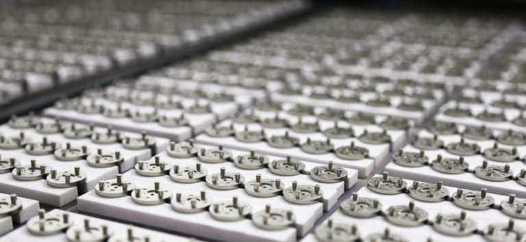
Shrink Effect
During sintering stage, shrink effect is inherent to MIM process. Green Parts will shrink on tiles when place into ovens with high temperature sintering. The Green Parts will shrink approximate 20% on average, specific shrink rates are determined by material grades and sintering temperature. Shrink effect is critical for MIM parts with high tolerance requirement. Our engineering team will investigate MIM parts design with shrink factor influence, in order to guarantee our MIM parts have high accuracy on both dimension and target.
The design should allow standard or flat debinding and sintering supports, avoids custom or part-specific support with additional tooling cost for final parts production. Part specific supports will be required for special parts structure while single flat or plane cannot be provided. Ceramic strip as the simplest support are in different heights and widths to satisfy finished parts various dimensional requirements.
But these ceramic plates with machined or cast features increase both complexity and cost. In order to minimize ceramic cost, features like drilled holes, drilled pockets or machined posts are all perfect options for complex parts support with cost limitation.
Otherwise, ceramic strips can be avoided by adding molded-in supports, add non-functional features to the component while eliminate additional tooling cost.
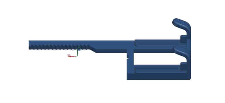
Sag Effect
During sintering process, high temperature will melt fine metal powders in brown parts. This will give rise to parts become relatively soft and deformable. In reason of gravity and vibration, cantilevered or unsupported features tend to flow or sag. In order to eliminate sag effect, we need consider gravity and vibration effect in MIM designing process. Special centers or ceramic should be added maintain those unsupported features, which can be individual blocks or custom machine ceramics.
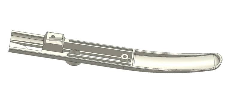
Another option is assisting you to modify design, in order to accommodate MIM parts function without any additional cost. We recommend adding features like gusset on sag area, this is perfect if parts form and function will not be effected.
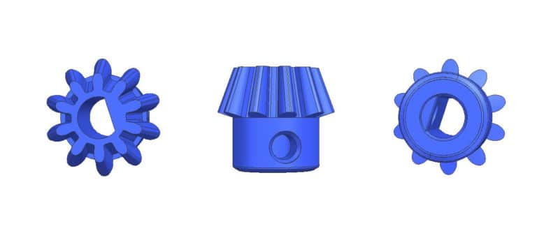
Draft Angles
Although in MIM design process, we recommend little draft angles, but there are some MIM parts can be designed with no require draft. As post molding parts shrink before ejection process, and polymer binder as lubricant will assist molded parts eject easily from mold cavity. However, features with high aspect ratio like thin wall section or long core pin, must require a draft angle following design guideline principle.
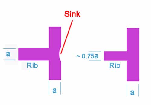
Wall Thickness
Uniform wall thickness is ideal for MIM design as following recommendations in MIM design guidelines. It is convenient for us to control the shrinkage variability. such as:
Gating
Solving functional or assembly issues
Knurling
Custom feedstock

Undercuts
In ZCMIM, we can design MIM parts with collapsible cores or sliders, which allows undercuts features in mold with function. Undercuts are challenging or impossible in other metalworking technologies, but it is definite doable with metal injection molding, no matter external or internal. In undercuts designing, we strongly recommend connection with our engineering team for professional MIM design advice.