Incipio Devices Medical MIM Case
Introduction
ZCMIM cooperates with thousands of enterprises to assist their new products’ development. Incipio Devices in Switzerland is a professional orthopedic device company, all their medical products require high accuracy, excellent mechanical properties and chemical resistance. Our experienced engineering team has ability to discover MIM technology potentiality, and create unique solution, and finally satisfy all customer specific requirement. In this Incipio Devices new case, we plan different MIM manufacturing methods, verify manufacturing possibility, and provide the most cost-effective way with high productivity.
Case Analysis
Complex Structure
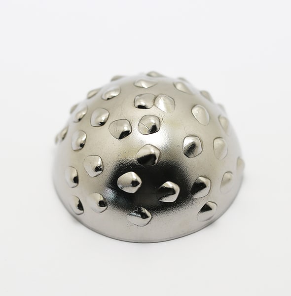
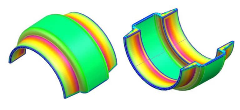
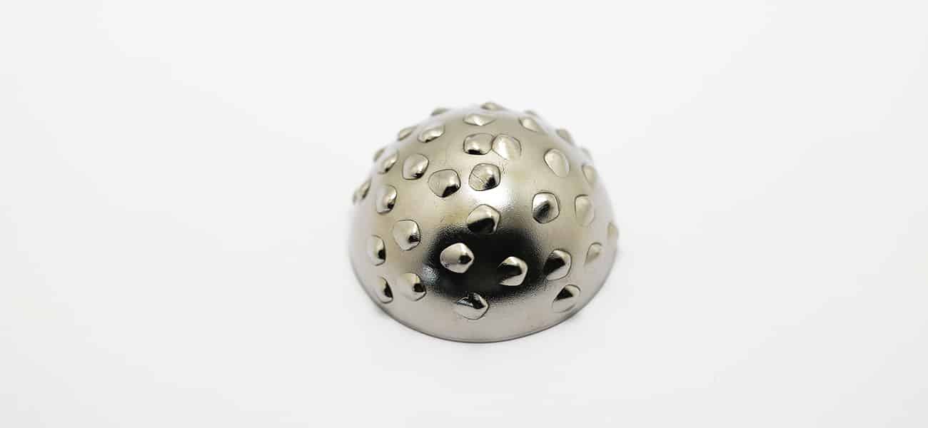
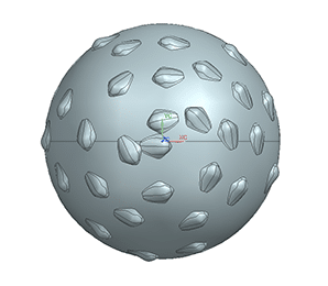
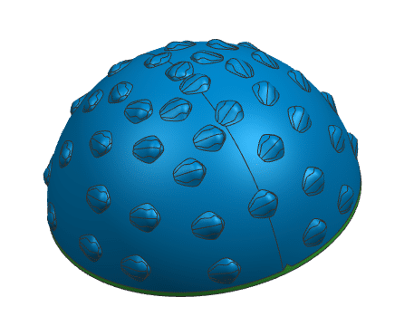
As the 3D section visions form different axis, we can easily notice that the complex structure of this medical MIM part.
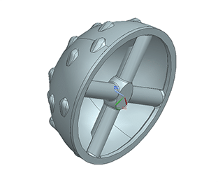
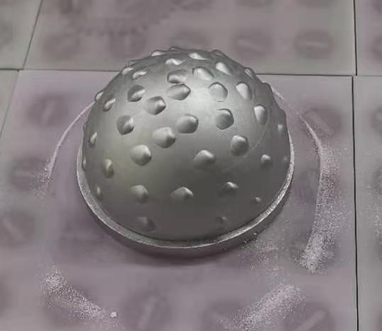
1. The main medical structure is a hemisphere.
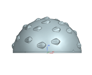
2. On hemisphere surface, there are particular tooth features with according position.
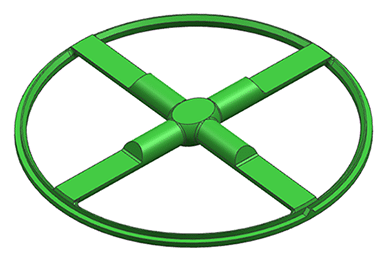
3. On cross-section of hemisphere area, a specific crossbar structure is added.
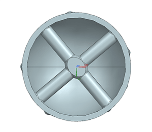
4. This specific crossbar structure has shape transformation from cylinder to half cylinder on crossbar beams. In addition, crossbar joint area has distinct shape requirement.
High Tolerance
Regardless of the complex structure of this case, from the 2D drawing files, we also achieve the high tolerance demand in this MIM parts.
1. The surface profile tolerance of sphere and hemisphere is 0.2, and diameter tolerance is ±15 mm, radius tolerance of hemisphere is ±0.10 mm.
2. Crossbar beam’s width tolerance is 0 mm to -0.05 mm.
3. Total 40 teeth, its tolerance is ± 20 mm in length and ± 0.20 mm in width, and the tooth position tolerance is ± 0.05 mm. In addition, the thickness tolerance of hemisphere is ± 0.05 mm.
Medical Demands
In reason of this MIM part medical application, we should notice additional demands in MIM manufacturing process.
- MIM materials(MIM feedstock): medical devices require specific MIM metal with bio-compatibility.
- Mechanical properties: in this case, all tooth need higher hardness than normal standard.
- Corrosion resistance: this MIM part is applied to transplant into human body, so chemical resistance should be considered carefully.
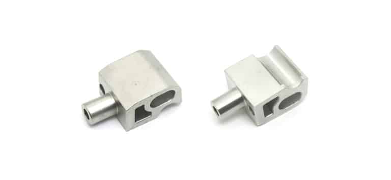
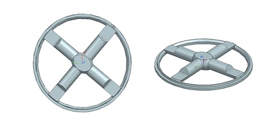
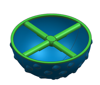
Design for Manufacturing
Consider the actual MIM process includes injection molding process, this part is difficult to finish as whole in one step. The most cost-effective way is to separate this part into hemisphere and crossbar. In this case, we can easily eliminate effects in MIM design, such as parting line, thin wall thickness, gating.
MIM Manufacturing Process
MIM Feedstock Selection
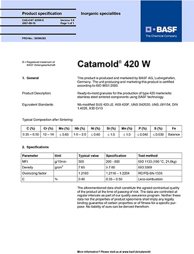
According to customer specific material requirement, feedstock supplier must be BASF, and material must meat ISO 7153-1 or ASTM F899. We select the MIM feedstock of BASF Catamold 420 W. Detail specification is in following picture:
Injection Molding
In normal MIM process, we will optimize MIM designs for MIM injection molding possibility. In this case, we notice that there is no way to inject the whole part in one time. Complex shape structure with different features limit the injection gate and ejector positions. Otherwise, consider the actual injection molding process, we recommend finishing it in two injection ways.
1. Injection molding the hemisphere structure
2. Injection molding the crossbar area.
3. Assemble hemisphere and crossbar.
Debinding Process
As we apply BASF material in this case, so the corresponding debinding technology is catalytic debinding. In samples debinding process, there are different issues affect parts formation and tolerance.
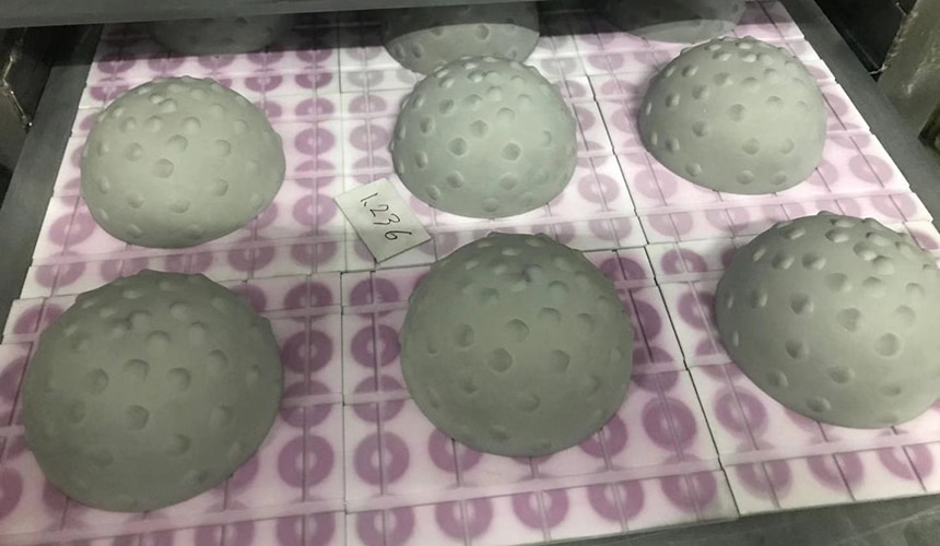
1. Asymmetric shrinkage: In debinding process, there is slight shrinkage of injected part (green part). Because of the complex structure in this case, hemisphere formation is easily affected by green part placement method, ceramic tray. According to our sample tests, the optimum option is ensuring that both furnace and ceramic tray are absolutely clean without any other impurities remain, meanwhile place green parts as following picture with ceramic grid tray.
2. Debinding time & temperature: These two factors determine the efficiency of debinding, then determine sintering performance, result to carbonization on sintered part surface. In this case, our debinding parameter is 110℃ for 5 hours with nitrogen atmosphere.
Sintering Process
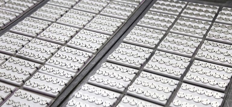
As high accuracy requirement in this case, final sintering process is critical for final parts quality. From sample testing data, our engineering team confirm the perfect placement of (debinded parts) brown parts, in order to avoid deformation because of shrinkage.
- 420W material plates are applied to support brown parts.
- Add ceramic sand between 420W material plates and brown parts.
- Finally, place 420W material plateand brown parts in one ceramic tray for sintering.
There are various issues in sintering process.
- Friction between brown parts and ceramic tray, will affect isotropic shrinkage in sintering. Finally result to deformation.
- Sintering temperature: in this case, BASF recommend sintering temperature at 1350℃
In our sample test process, our engineering team alter this temperature to 1360℃. Otherwise, there is an integration issue between hemisphere and crossbar.
- Sintering time: In sample test, we notice that too long sintering time will result in sink of hemisphere, and deformation of crossbar beams. More serious, sinted part will be broken down. On the other hand, too short sintering time will give rise to surface performance issue on hemisphere, injection mark is visible.
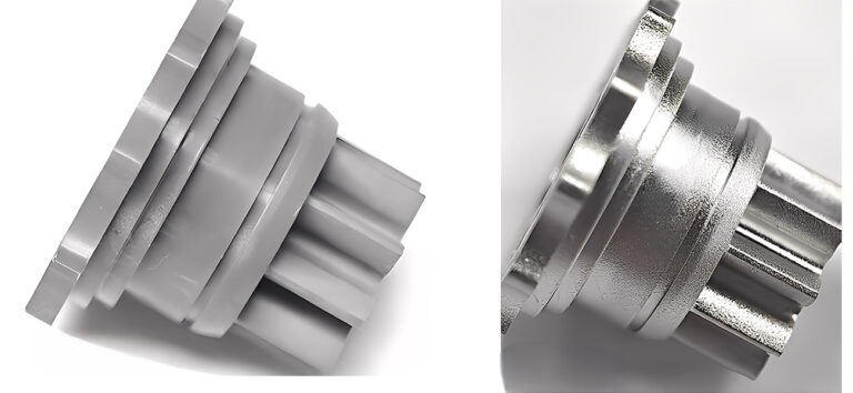
Shaping Process
In this case, the tolerance of complex features are higher than normal products. After sintering process, sintered parts can not achieve tolerance demand, so additional shaping process are required to increase accuracy, especially for tooth features.
Before shaping, all sintered parts will go through an annealing process to reduce hardness and increase shaping efficiency. According to our hardness test, sintered parts surface hardness will reach to more than 44HRC, while after annealing process, its hardness reduce down to only 17-18 HRC.

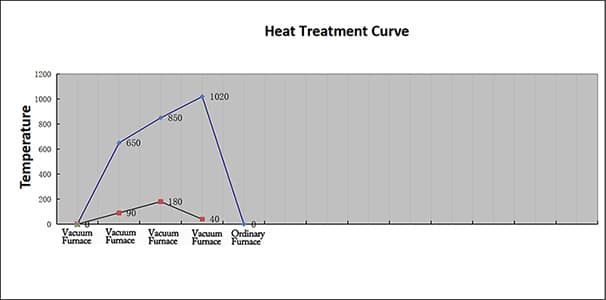
Heat-treatment (tempering) Process
As this case require specific hardness requirement, especial for tooth area. Heat treatment technology as tempering is applied to increase surface hardness. After our specific tempering process, tooth hardness can reach to approximately 50 HRC.
Our tempering parameter as following:
Conclusion
Although, this Incipio Devices medical case is more difficult than our normal MIM projects. ZCMIM engineering team still finish it with high reputation. Excellent experience encourage our team to discovery the most cost-effective solution to satisfy any requirement of our customers.
If you are looking for a professional MIM supplier for your next project, why not contact us now.