Optimize MIM Design
Introduction
As the global MIM industry developed dramatically in the last 20 years. MIM market acceptance and awareness had achieved at a high level. Many designers can identify parts which are candidates for metal injection molding process at early designing process. This provides an excellent opportunity for MIM manufacturers to produce successful MIM components. Furthermore, ZCMIM engineering team notices the basic consideration to optimize MIM design, in order to guarantee our MIM parts quality and performance.
ZCMIM as a professional MIM company in China, has more than 10 years experience in MIM manufacturing. Our engineering team notices the basic consideration for MIM parts design and specification as following. In order to guarantee our MIM parts quality and performance. All these factors will affect the manufacturability of MIM parts. Then impact MIM manufacturing cost, quality and lead-time. These factors are general observation in the typical MIM process, but are easily to overlook.
Suitable MIM Material
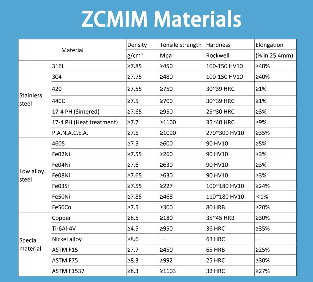
As various MIM metal with unique properties are widely applied in MIM manufacturing process. We recommend select your MIM materials with industry support and documentation. This will avoid conflict in unrelated design requirements. Such as, once you need a special design with heat treated low alloy steel with strength and hardness requirement. However, there is no doubt that in MIM sintering process, the temperature is typically over 500℃ for a time of 1 hour or longer. It means the heated treated steel is no longer as start.
Never Over-specify Tolerances
In MIM designing process, we always want to specify an ultra-accurate part. In reason of MIM is an extreme precise net-shape manufacturing process. However, this will come at the expense of more complex production and more additional cost. There is an overlooked item result to this result by over stringent default tolerance in drawing. Such as replace normal tolerance of ±0.05 mm with higher specific tolerance of ±0.025 mm. These higher specific tolerances are global standard, where non-critical features have more tight tolerance than critical-to-function features that designers have specified directly. So first prototyping will be delayed and molds require rework to achieve tolerance requirement, just in reason of this over-specify tolerance for no function features.
Nominal Part Requirement
MIM tolerance has a +/- variation on the standard shrinkage from molds. The basic reason is that molded and sintered parts have slight density volatility, which will make individual parts larger or smaller on size dimension. However, in MIM parts design drawing, the designers should specify tolerance to show design intent.
For example, if there is a 50.00 mm dimension in MIM parts, while the designers don’t want this dimension to exceed 50.00 mm. So there will be an unbalanced tolerance of 50.00 mm +0.00 mm, -0.50 mm. In order to notice the allowable tolerance is 49.50 mm -50.00 mm, the nominal dimension is 49.75 mm. Once we create MIM molds by this design tolerance of 50.00 mm, there is no doubt that a lager percentage of final parts will be outside this specification. We recommend a better balanced tolerance option of 49.75 mm ±0.025 mm. In order to guarantee the MIM molds will reflect final parts nominal.
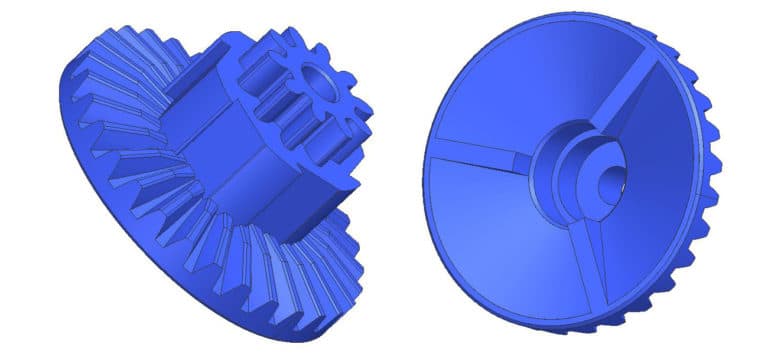
Shrinkage Isotropic
There is common knowledge in MIM industry, most MIM process will produce parts with different shrinkage on different axes. These shrinkage rates are difficult to predict in advance. Once you design a part with nominal dimension at three axes, the final sintered part will only center on nominal dimension at one axis. The other two dimensions will be either higher or lower. In addition, this process is also stale, all suboptimal dimension in parts are repeatable in the same gated and molded orientation.
This issue should be noticed for high tolerance requirement, we need molds modification to optimize all dimensions. Comparing to other technologies, MIM is lack of cylindrical accuracy.
Critical Dimension Optimization
Due to non-isotropic shrinkage or other issues in sintering process. MIM sample parts are not centered in the desired nominal dimension. As in strict dimensional control requirement, we should adjust tooling molds to satisfy the dimension requirement.
Molds adjustment require either adding or removing materials in cavities. In adding process, we apply welding process to add steel into molds cavities. There are some critical issues with welding, such as damage to underlying or adjacent cavity steel, long-term adherence of weld materials and underlying metal. This process will add time and expense, entail long leading time and high cost.
It is difficult to modify molds by material adding, but easier to remove. We should review part molds to identify critical dimensions, then optimization to get nominal in sintering process. Such as internal features of diameters and slots, external dimension of parts length or diameters.
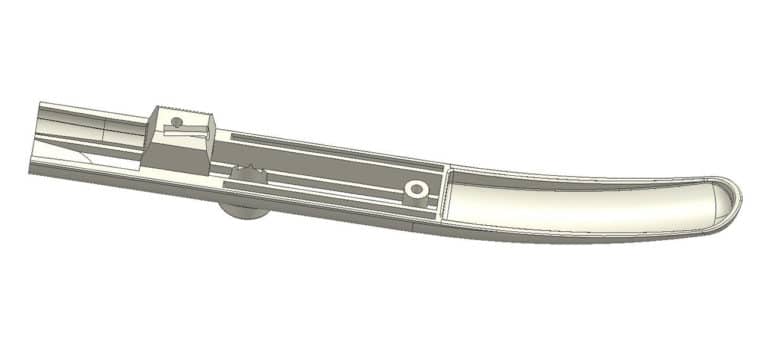
Inspection and Verification Requirement
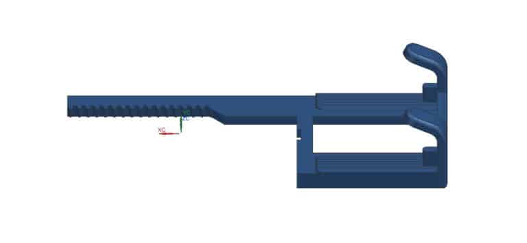
3D modeling makes the complex parts design easier in designing process. This will create complex geometries in MIM parts designing process, it is common and useful to design features like blended surface with visual appealing for functional components. However, we should also consider the difficulty of surface inspection and quality control issues. Such as the curved finger surface has constant radius alternatives forfromm tip to base. As this difficult-to-inspect requirement is not critical to parts performance, we should discuss this issue before the MIM projects start. In order to establish acceptable rules before complication arise.
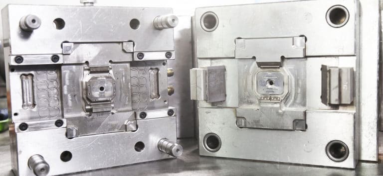
Parting Line, Ejector Pin and Gate
No matter in plastic injection molding, die casting or MIM. We should realize that all parts are created by convey materials through molds. So we need to notice that:
Gate: which introduce materials into molds cavity.
Parting line: which are created by different sections of molds once open.
Ejector: which push out cooled molding parts.
These three element gate location, parting line and ejector location have a major effect on final parts quality, mold cost and life.
We should avoid putting gate or parting line on a critical surface, in order to eliminate issues of unacceptable function variation. The following consideration should be noticed in MIM design process:
- Designers must notice which part surfaces are critical.
- Molds manufacturers must communicate their plan to produce mold cavities.
- MIM manufacturer must ensure the reliable MIM mold production to maximize productivity and quality.
Shrinkage Issues
In MIM process, there are 3 stage of part shrinkage:
Molding Shrinkage
MIM parts will shrink from mold cavity dimension to as-molded parts, this shrinkage is in the range of 0.3-0.5%, it is a minor factor in overall dimensional variation.
Debinding Shrinkage
This is a minor shrinkage, sometimes, this will result to dimension growth rather than shrinkage.
Sintering Shrinkage
This is the dominant factor for dimension shrinkage from molds cavity to finished parts. As significant density variation, there will be 15-20% linear shrinkage.
This is the dominant factor for dimension shrinkage from molds cavity to finished parts. As significant density variation, there will be 15-20% linear shrinkage.
Coining Process
The operation of coining is prevalent in MIM industry. There are different level of warp or distortion in MIM process, in reason of part shrinkage of 15-20% in sintering process. Coining operation will correct distortion into original non-distorted by physical method.
During the coining process, the applied force should exceed the material’s yield strength significantly. Otherwise, the parts will spring back and return to its sintered dimension. There is an effective way to minimize spring-back variation, select the alloy with lowest as-sintered yield strength. Such as, SS 316L and SS 17-4PH are common MIM stainless steels with effective corrosion-resistance. While SS 316L has lower sintered yield strength, it will have better desired shape performance than SS 17-4PH.
Mold Filing Integrity
Once the designers want to take on more challenging parts, we should take care to ensure parts can be molded with sufficient material integrity. There are several attributes will cause molding problem as following:
Thin sections: Most MIM feedstocks will fill section with 0.3 mm thin. However, the longer distance will increase the challenge of non-fill issues.
Weld lines: This issue occur in separate material flow meet area, it will cause degradation of strength and surface finish.
Internal sharp corners: This will raise stress and give rise to crack and low strength properties. So radii with minimum 0.1 mm in molds will reduce risk.
Proper venting: The entrapped air in cavities need to be escape once cavities are filled with molten feedstock. In order to ensure materials fill the cavity completely. The vent, which is as thin as 0.01 mm, can allow air to escape and also prevent flash formation.
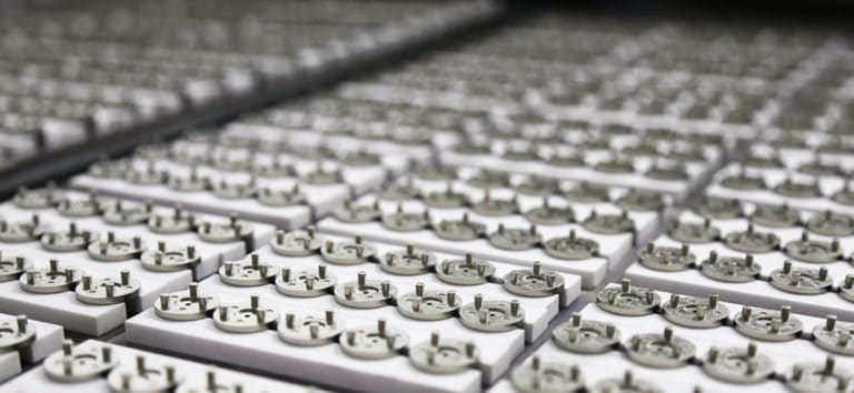
Conclusion
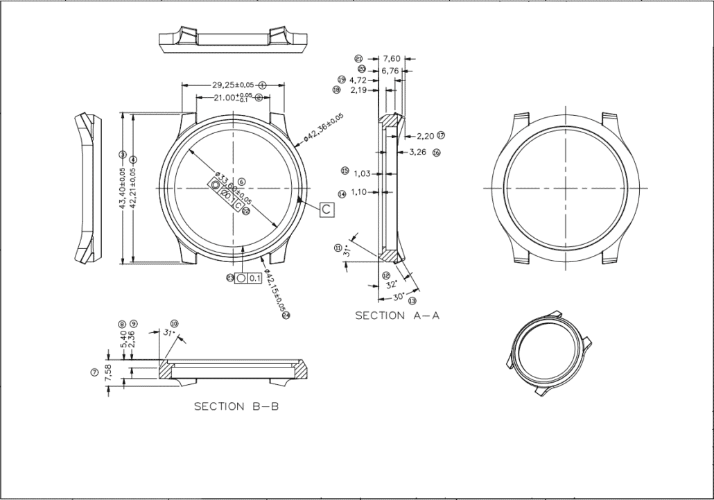
MIM parts are all around us in everyday lives, from watch case to automotive components and surgical devices. So designers should consider the basic of Optimal Design of MIM, in order to guarantee the smooth MIM journey with time and money saving. Once you recognize your parts is a candidate for MIM. Please contact our engineering team to open up your design ideas.